
The turbine converts kinetic energy from the wind into three-phase AC electrical energy.
The wind turbine cost for a 10MW wind turbine is about £10 million. This includes components as well as assembly and wind turbine supplier aspects of installation and commissioning, plus warranty provision. These installation and commissioning costs relate mainly to own logistics and staff costs at head office, the construction port, on the installation vessel and on the turbine relating to mechanical and electrical completion, testing and pre-handover checks and trouble shooting. These costs typically exceed £1 million per turbine.
Europe: GE Renewable Energy, Vestas and Siemens Gamesa Renewable Energy (SGRE). MingYang signed MoU for UK blade manufacturing and turbine assembly in December 2021.
Asia: CSIC Haizhuang, Doosan, Dongfang Electric Corporation (DEC), Envision, Goldwind, Hitachi, Ming Yang and Sinovel.
Most designs have upwind, pitch controlled, variable speed rotors with three blades. Compared to onshore wind turbines, turbines are much larger and there is an increased focus on reliability and maintainability and a decreased impact of noise, visual and transport constraints.
Wind turbine suppliers are systems integrators. Blades are typically manufactured in-house, along with a few other components in some cases, depending on the industrial strength and breadth of the supplier.
There are fewer offshore turbine suppliers than onshore. The high investment costs, large project sizes but relatively low overall sales volumes make it difficult for new suppliers to challenge the incumbents.
A new generation of 12MW+ turbines has been developed and turbines with ratings at and over 14MW are offered by the main European suppliers. Typically, after a new turbine platform is developed, turbine variants are offered to the market with higher rating (or, more rarely, larger diameter) as their operation is better understood and the platform upgraded. This extends sales lifetime of a given platform while minimising development costs.
Wind turbine suppliers prefer to operate just one or two nacelle assembly facilities and blade manufacturing facilities for the European offshore market, as volumes are not that high and fewer turbines are needed per GW as turbine sizes increase. The choice of site depends on the size of the local market, the locations of key suppliers, skills availability and support for local job creation.
The design life of an offshore turbine is 25 years. The trend for longer design life on all turbines is due to the maturing of the industry – asset owners now expect to operate wind farms for such periods without the technology becoming obsolete or unsupported by suppliers. The design driver for many components is fatigue loading when generating. Extreme loads due to storms, abnormal events and faults during operation can also be critical. Typically, an offshore turbine will turn for over 90% of the time.
Asia suppliers are offering turbines better suited to lower average wind speed wind regimes with larger rotors for a given turbine rating.
Turbines are type certificated by third parties. This confirms that the wind turbine type is designed, documented and key features of performance verified in conformity with specific standards and other technical requirements. This certification also covers the suppliers of the key components.
Health and safety requirements are increasingly focused on safety by design where the need for people to be put in hazardous environments is minimised or avoided at the design stage.
The nacelle supports the T.2 Rotor and converts the rotational energy from the rotor into three-phase AC electrical energy.
The nacelle cost for a 10MW wind turbine is £4 million.
Nacelles are assembled by the wind turbine supplier, using components generally sourced from a range of external suppliers.
Typical dimensions for a 10MW turbine are 20-25m long x 9-12m wide x 7-9m high, with mass 400-500t including hub.
Nacelle mass is kept low to help with overall system dynamics and minimise logistics costs. To keep nacelle mass down, turbine designs may include the transformer and much of the power electronics in the tower base. Mid-grade steels and cast spheroidal graphite (SG) iron are used rather than low-mass materials as they offer the lowest cost per unit fatigue strength.
There has been a move away from high-speed gearboxes for offshore turbines. For example, GE Renewable Energy and SGRE have opted for direct drive turbines without a gearbox but instead with a larger and a more complex generator. Vestas has opted for turbines with a medium speed gearbox (600 rpm) and slightly more complex generator.
Before dispatch, the nacelle undergoes a functional test before being prepared for transport and storage. It is also typically tested with its power take-off hardware.
New designs of offshore turbines place a high emphasis on maintainability. This is being achieved through modular designs for large components so more subcomponents can be replaced using the nacelle crane. This minimises the need for jack-up vessels, which are expensive and may have lengthy mobilisation periods.
The nacelle incorporates high levels of remote monitoring, heath checking and control.
T.1.1 Bedplate
T.1.2 Main bearing
T.1.3 Main shaft
T.1.4 Gearbox
T.1.5 Generator
T.1.6 Power take-off
T.1.7 Control system
T.1.8 Yaw system
T.1.9 Yaw bearing
T.1.10 Nacelle auxiliary systems
T.1.11 Nacelle cover
T.1.12 Small engineering components
T.1.13 Structural fasteners
T.1.14 Condition monitoring system
The bedplate supports the drive train and the rest of the nacelle components and transfers loads from the rotor to the tower.
The bedplate cost for a 10MW wind turbine is about £200,000.
Bedplates are normally cast SG iron, with a steel fabricated rear section.
Casting: Eisengiesserei Torgelow, Felguera Melt, Fonderia Vigevanese, Gusstec, Metso, MeuselWitz, Sakana and Siempelkamp. Only some of these can manufacture the largest bedplates for offshore turbines today.
Fabrications: A reasonable range of steel fabricators exist capable of bedplate manufacture.
Frequently, bedplates are manufactured in two parts. The heavier section supports the T.1.4 Gearbox and the T.1.8 Yaw system, transfers loads from the T.2 Rotor to the T.3 Tower and is frequently cast. A lighter section supports the T.1.5 Generator and other components at the rear of the nacelle and is normally fabricated. For a direct-drive turbine, the generator takes the place of the gearbox.
Bedplates are designed by the wind turbine supplier and generally manufactured by sub-suppliers. Design considerations include fatigue and extreme loads, stiffness and assembly, and maintainability features such as access ways to critical components.
Once manufactured, the items are machined, shot blasted, metal sprayed and epoxy painted before delivery to the wind turbine supplier. Material is typically EN-GJS-400-18U-LT grade SG iron or a standard 355-grade steel.
Large SG iron or fabricated steel structure
Machining and painting
A number of auxiliary systems facilitate ongoing unattended operation of the wind turbine for the vast majority of the time, and support planned maintenance, which typically should be only on an annual basis.
The nacelle auxiliary systems cost for a 10MW wind turbine is about £70,000.
Brake: Siegerland, Stromag and Svendborg.
Cooling: Hydac, Windsyn.
Air conditioning: Cotes.
Anemometry: FT Technologies, Gill Instruments, Kipp & Zonen, NRG Systems, Orga, Thies, Vaisala and Vector Instruments.
Lidar: Leosphere (Vaisala), Wood and ZX Lidars (Fred. Olsen).
Fire protection: Danfoss, Firetrace and Minimax.
Uninterruptible power supply (UPS): AKI Power Systems.
Internal service crane: Effer, Hiab, Liftra and Palfinger Marine.
Typically, a mechanical brake is mounted at the rear of the T.1.4 Gearbox. Primary braking of the wind turbine in the event of an emergency is achieved by pitching the blades. In some cases also electrodynamic braking is used but a mechanical brake is also present, frequently with a hydraulically applied callipers acting on a disk.
A rotor lock enables locking of the rotor in a fixed position for maintenance activities. Typically, for large turbines it consists of a peg-and-hole arrangement with manual or automatic hydraulic actuation engaging one or more pegs with holes on the front flange of the T.1.3 Main shaft.
A large offshore turbine is about 92-94% efficient in converting kinetic energy in the rotor to electrical energy, requiring at times up to 800kW of heat to be dissipated from gearbox, generator and electrical system.
To protect all nacelle components from corrosion, the nacelle is well sealed and the whole area is served by a local air conditioning system.
Mounted on the roof of the nacelle is an anemometry mast with sensors measuring wind speed and direction. Frequently, these functions are combined into sonic devices, rather than using traditional cup anemometers and wind vanes.
Frequently, fire protection systems are provided in order to sense and suppress fire in different areas of the turbine. Within electrical panels, nitrogen is used. In open spaces such as the nacelle, fine water spray systems are employed. The fire protection systems have separate control and condition monitoring from the turbine controllers.
To facilitate orderly shutdown of the turbine under grid loss conditions, UPS systems are used to power the control, safety and emergency systems and provide emergency lighting in the tower to facilitate safe exit of personnel. In some cases, UPS power is required in order to ensure requirements for rotor warning lights on the tips of blades continue to operate for an agreed period.
The internal service crane for a large turbine is designed to lift key turbine components during maintenance activities, typically up to 10 tonnes. The crane is controlled wirelessly and operates through cut-outs in the nacelle cover to lower components to the access platform.
Brake
Rotor lock
Cooling
Anemometry
Fire protection
UPS
Internal service crane
The nacelle cover provides weatherproof protection to the nacelle components plus support and access to external components such as coolers, wind measurement equipment and lighting protection devices.
The nacelle cover cost for a 10MW wind turbine is about £100,000.
Bach Composites Industry, Eikboom.
As well as providing environmental protection, frequently it supports lighting and other auxiliary supplies and acts as a faraday cage to protect nacelle components from lightning damage.
It is fitted during assembly of the nacelle, either before or after final test, and plays a valuable role in protecting nacelle components during transport to the wind farm site, as well as during operation.
It is designed to withstand wind loading and provide access to lifting points on the nacelle T.1.1 Bedplate for transport and installation.
Careful design also facilitates exchange of nacelle components through hatches or hinged openings in the roof, side or floor.
The nacelle cover is typically manufactured in a number of sections from glass fibre or steel and may have mass up to 20 tonnes.
Fibreglass or steel construction
Built-in or post-assembled auxiliary systems (for example lighting)
Maintenance support features
A range of frequently standard engineering components makes up the rest of the nacelle assembly.
The small engineering component cost for a 10MW wind turbine is about £250,000.
Many items are off-the-shelf or can be manufactured by a range of metalworking companies.
Guards and flooring and maintenance aids are normally fabricated to drawing from steel or aluminium.
A range of cable / hose handing systems, air ducts and similar are needed, depending on nacelle layout.
Anti-vibration mounts support the T.1.5 Generator and sometimes other critical components.
Standard industrial lighting systems are used to facilitate maintenance work.
Fasteners typically vary from M6 upwards and may be grade A4 stainless or galvanised.
Guards, flooring, drip trays, cable and hose handing systems and other fixed maintenance aids
Anti-vibration mounts
Lightning conductors
Small fasteners and other accessories and consumables used during nacelle assembly
Fasteners (either bolts or studs) are used in a range of critical bolted joints, for example connecting rotor to main shaft, main bearing housings to nacelle bedplate and yaw bearing to the underside of nacelle bedplate.
The structural fasteners cost for a 10MW wind turbine nacelle is about £70,000 (similar for rotor and included in total rotor cost).
August Friedberg, Cooper & Turner, Fuchs & Sanders, Gexpro Services and Multifix.
Fasteners for critical structural joints within large turbines are typically of size M30 or M36 and grade 10.9.
Often, the fasteners are specified to have threads rolled after heat treatment to improve fatigue properties.
Coatings provide corrosion protection.
All critical structural fasteners are preloaded either using hydraulic torque tooling or (in the case of studs) hydraulic tensioning. Increasingly, preload indicators or other visual checks on tightness are used.
Bolts
Studs
Nuts
Condition monitoring systems provide additional health checking and failure prediction capability.
Brüel & Kjær Vibro, Gram & Juhl, SecondWind and SKF.
Condition monitoring systems frequently make decisions about individual components (such as the gearbox) via sensors measuring parameters for that component. They also use a range of sensor and controller outputs and make holistic decisions about all drive train components.
Condition monitoring systems on the T.2 Rotor are able to assess control behaviour as well as blade health.
Turbine and condition monitoring systems send data to cloud-based databases to facilitate analysis over a wind farm and a larger number of turbines. Results of the analysis can lead to changes in control reducing loads on a failing component. Better understanding of the condition of the turbine drive train can lead to increased power output under some conditions where the fatigue life of the turbine allows.
Sensors
Condition monitoring hardware and software
The main bearing supports the rotor and transfers some of the rotor loading to the nacelle T.1.1 Bedplate.
The main bearing cost for a 10MW wind turbine is about £200,000.
Liebherr, Schaeffler, SKF and thyssenkrupp.
A number of different bearing arrangements exist for offshore wind turbines including a single bearing supporting the generator and rotor. Another approach is to support the T.1.3 Main shaft with a bearing at each end.
Such arrangements may use a combination of spherical roller bearings (to provide axial location) and a self-aligning roller bearing. Tapered roller bearings, such as the two-row double-outer race (TDO) and tapered double inner (TDI) variants, are also used to manage the combination of radial, thrust and overturning loads. Bearings are often heated prior to mounting on the main shaft in order to provide a robust, stress-concentration free connection.
Cast-iron bearing housings provide stiff supports for these bearings and connection to the nacelle bedplate.
Forged rolled ring, machined and hardened
Rolling elements (spherical, crowned cylindrical / tapered)
Rolling element support (cage)
Lubricants and seals
SG iron bearing housing
The main shaft transfers torque from the rotor to the gearbox or, for some direct drive designs, the generator. It is supported at the rotor end by the main shaft bearing and at the other end either by the gearbox / generator or separately mounted bearing.
The main shaft cost for a 10MW wind turbine is about £200,000.
Brück, Euskal, Skoda and thyssenkrupp
Conventionally, the rotor is flange-connected to the main shaft using a single or double row of T.1.13 Structural fasteners. The main shaft normally also has a ring of holes for use in positively locking the rotor in fixed position for maintenance activities.
It normally has a central bore through which control signal, control power supply and electrical or hydraulic power cables are passed to the hub for operation of the blade pitch system.
For a large 10MW turbine, the main shaft may have a mass of over 50t and be forged and machined from high-grade steel such as 42CrMo4 or cast hollow from EN-GJS-400-18U-LT. Different turbine concepts require quite different main shaft designs.
Even for such a large item, fatigue loading is important as the rotating shaft is supporting the mass of the rotor as well as resisting the aerodynamic torque and thrust loads. It is critical to minimise stress concentrations.
Forged / cast shaft
Machining, NDT and painting
Where used, a gearbox converts rotor torque at a speed of 5-15 rpm to a speed of up to about 600rpm for a medium speed gearbox and 1500rpm for a high-speed gearbox for conversion to electrical energy by the generator.
The medium speed gearbox cost for a 10MW wind turbine is about £700,000.
Winergy and ZF
The gearbox is a critical item in the wind turbine drive train, with much attention given to the long-term operation given a history of variable quality and reliability.
Typically, designs incorporate a planetary first stage followed by a higher-speed parallel (helical) stage. Normally, a brake disk is mounted at the rear (high-speed) end.
Design drivers include peak torques coming from a range of load cases; also loads in storms and during braking or other abnormal events, and avoiding high speeds in the gearbox itself.
Careful consideration is given to the variation in bearing and gear contact points due to a wide variation in operating power levels during turbine life, including periods of standstill and operation under minimal loading, introducing the possibility of skidding within bearings.
Design methodologies couple empirical rules of thumb, detailed dynamic analysis and workshop testing.
Automatic heating is frequently applied before restart in cold conditions and cooling is designed typically to keep operating temperatures below 70˚C. Cooling systems may be combined with that of the generator.
Lubricants specific to wind turbine gearboxes have been developed, with reduced end of life environmental impact.
Typically, the gearbox has a bore (say 100mm) in the central shaft (along the axis of the main shaft) to facilitate provision of control signal, control power supply and electrical or hydraulic power cables to the hub for operation of the blade pitch system.
SG iron castings (including higher grade (say EN-CJS-700-2U) for items such as planned carrier) and steel forgings
Cylindrical, taper and spherical roller bearings; plain bearings
Gears
Lubricants
Sensors
The generator converts mechanical energy to electrical energy.
The medium speed generator cost for a 10MW wind turbine is about £1 million. The direct drive generator cost for a 10MW wind turbine is over £2 million.
Suppliers include ABB, Elin, GE, Ingeteam, Leroy Somer and VEM.
Most generators use permanent magnets that need no excitation power. This keeps weight low and dimensions small, lowering transport and installation costs but does rely on the supply of alloys of rare-earth elements.
All operate at variable speed, with grid connection via an AC-DC-AC converter. This enables the smoothing of drive train loading and the optimisation of aerodynamic performance without the need for a variable ratio gearbox.
Efficiency is critical, especially at part load, as a wind turbine spends many hours generating 20% to 80% of rated power in low-to-medium wind speeds.
Water-cooling is common in order to maximise efficiency and compactness whilst limiting noise levels.
Generator bearings are designed to avoid passage of electrical current and with special emphasis on lubrication. Typically, these are specialist deep-groove bearings, sometimes with ceramic rolling elements.
Related, but not part of the scope of supply of the generator, is the coupling that connects the generator to the gearbox. As both components are flexibly mounted and the wind turbine structure is relatively flexible compared to the loading applied, such couplings generally are able to cope with substantial misalignment.
Castings
Windings
Bearings
Sensors
Slip rings for doubly-fed induction generators
High-speed shaft coupling
The power take-off receives electrical energy from the generator and adjusts voltage and frequency for onward transfer to the wind farm distribution system.
The power take-off cost for a 10MW wind turbine is about £700,000.
Power converters: ABB, AVK SEG, GE Power Conversion, Ingeteam and The Switch.
Transformers: ABB, CG (Pauwels), GE Power Conversion, Schneider Group, SGB and Siemens Power Transmission and Distribution.
Switchgear: CG (Pauwels), GE Grid Solutions, S&C and Siemens Power Transmission and Distribution.
Cabling: Nexans, NKT and Prysmian.
Most wind turbines have variable speed generators connected to the grid via AC-DC-AC power converters. There is a range of different generator/converter architectures used. With high power density, today’s insulated-gate bipolar transistor (IGBT)-based power converters frequently are water-cooled.
Critical to consider in the design of power converters are requirements imposed by grid operators for wind turbines to support and stabilise the grid during grid faults and to provide or consume reactive power on demand. Some convertors may be split between nacelle and lower tower section to reduce tower head mass.
Where the turbine voltage rating does not match that of the wind farm array, transformers are often placed in the T.1 Nacelle, or sometimes at the base of the T.3 Tower. Typically, they transform from low-kV (0.69kV to 3.3 kV) to 33kV or 66kV for distribution around the wind farm array and are of dry (cast resin) design, meeting detailed corrosion, environmental and combustion requirements. Typically, they are forced-air cooled.
Switchgear is designed specifically for wind turbine applications, for example gas-insulated for compactness and safety at up to wind farm distribution voltage.
Down-tower cabling is routed to enable the cables to twist, allowing the nacelle two complete revolutions of movement by the T.1.8 Yaw system before an untwisting operation is required.
Power converter
Transformer
Switchgear
Cables
The control system provides supervisory control (including health monitoring) and active power and load control in order to optimise wind turbine life and revenue generation, while meeting externally imposed requirements.
The control system cost for a 10MW wind turbine is about £250,000.
Bachmann, DEIF, KK-Electronic and Mita Teknik.
The control system carries out regular health checking using 100s of sensors monitoring key components and sub systems. In response to unexpected data, it takes decisions to curtail operation and provides regular reporting to the Supervisory Control and Data Acquisition (SCADA) system.
The control system also takes control input from the SCADA system, for example to derate wind turbines in response to utility customer requests. Increasing turbines have a power boost capability where they will generate at higher powers in benign conditions when parameters such as temperature and wind shear are in acceptable ranges.
Key control parameters for active power and load control are rotor speed, output power and the pitch angle of each blade.
Control intelligence may be distributed around the turbine, including in the hub. Control panels contain in-in-house designed and standard panel hardware to interface with sensors and auxiliary systems and combined may weigh up to 500kg.
In parallel to the control system, a safety system protects the turbine from control system or operator error. Key sensors for this overriding safety system include speed and vibration sensors. An emergency system with physical press-button and/or chord inputs is provided to bring the rotor to a halt in the event of risk to maintenance personnel.
Lidar is starting to be used to measure the incoming wind flow and/or the alignment of the nacelle relative to the wake and provide this data to the control system.
Each wind turbine can operate independently from external intervention, starting and stopping in response to changing wind conditions. Control at a wind farm level is used to optimise energy production and minimise loading, for example by avoiding turbines sitting in the wake of turbines immediately upwind.
Control panels
Control system hardware and software
Sensors: Accelerometers, load cells, power meters, strain gauges, thermocouples, and tachometers
Safety and emergency systems
The yaw system orients the nacelle to the wind direction during operation.
The yaw system cost for a 10MW wind turbine is about £170,000.
ABB, Bonfiglioli, Bosch Rexroth and VEM.
The yaw system typically consists of about 10 geared electric motors mounted on the nacelle T.1.1 Bedplate, with gear mounted on their shaft acting on the toothed inner ring of the T.1.9 Yaw bearing. Each drive has mass up to 1 tonne and typically has ratio 200-300:1.
To avoid constant varying loading on the drives, a series of about 10 calliper brakes are hydraulically applied to hold the yaw bearing in position, except when movement is required. Even during movement (which may be the order of a few degrees every few minutes in order to align the nacelle to the wind direction), the yaw brakes act to damp movement.
Sensors measure the position of the nacelle and limit switches prevent over-twisting of the cables down the tower.
Some wind turbines use hydraulically operated yaw motors, providing compliance to relieve tower top loading.
Yaw motors and associated gearboxes
Yaw brakes, sensors
The yaw bearing connects the nacelle and tower, enabling the yaw system to orient the nacelle to any wind direction during operation.
The yaw bearing cost for a 10MW wind turbine is about £70,000.
IMO, Liebherr and thyssenkrupp.
Bearings are typically single-row 4-point contact ball bearings made from forged rings of up to 6m diameter for a 10MW turbine, typically of a 42CrMo4 steel, quenched and tempered. Balls are typically material 100Cr6. Total bearing mass may be up to 10 tonnes. Raceways are hard-turned or ground after induction hardening.
Bearings see a complex load pattern and operate with long periods of no or only occasional movement over a small proportion of a revolution. Critical to long-term performance is the provision of flat mounting surfaces (so the tower flange will be machined after welding).
Bearings incorporate gear teeth to mesh with the yaw drives.
Forged rings, machined, hardened and surface finished
Balls
Cages / spacers
Seals
Grease
Metal sprayed and/or painted finish
The rotor extracts kinetic energy from the air and converts this into rotational energy in the drive train.
The rotor cost for a 10MW wind turbine is about £1.9 million.
Wind turbine rotors are usually designed and supplied by the wind turbine supplier as part of the complete wind turbine.
The T.2.1 Blades are connected to the turbine drive train via a central hub. In all offshore wind turbines, the blades are mounted on T.2.3 Blade bearings to allow independent adjustment of the pitch angle of each blade.
Fasteners are used to connect the blades to blade bearings and blade bearings to hub. These are typically M30 or M36 grade 10.9 bolts or studs (see T.1.13 Structural fasteners).
A rotor for a 10MW turbine has a mass of about 150t and a diameter of 170-200m.
There are no fundamental limits to the size of rotors for offshore turbines, though for the same design, mass increases faster than the additional energy generated (because energy capture is proportional to the two-dimensional swept area (square) but the blades increase in size (and mass) in three dimensions (cube). Substantial improvements in blade technology have meant that, so far, the actual increase in mass has been limited to nearer the square than the cube of blade length.
New turbine designs have larger rotor swept areas compared to their generator rating to achieve a higher capacity factor. Many offshore wind farms report capacity factors of about 50%, and above that is expected for the next generation of turbines. This compares with capacity factors of about 35% for good onshore sites.
As turbine rotor diameter increases, with the same limit on tip speed, the rotational speed will decrease. Lower rotational speeds make it more difficult to design a support structure that avoids resonant frequencies excited by loading from waves and operation of the turbine itself.
Rotor speeds are 5 to 12 r/min, resulting in a maximum tip speed of over 100 m/s.
In UK, rotor clearance must be at least 22m above mean high water springs (MHWS).
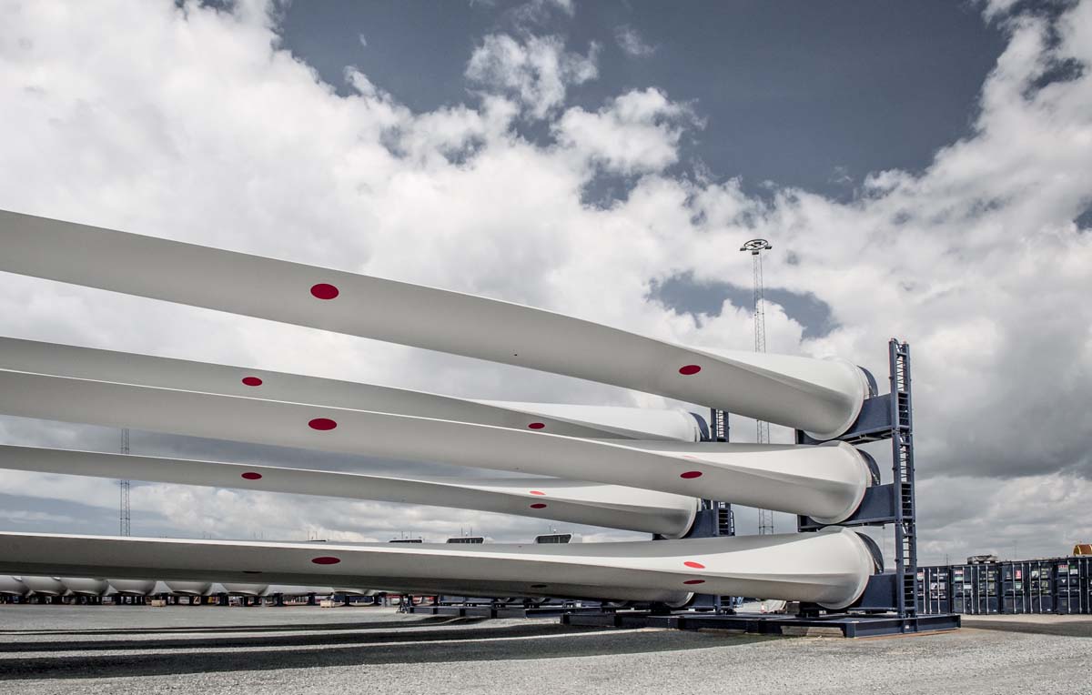
The blades capture the energy in the wind and transfer torque and other unwanted loads to the drive train and rest of the turbine.
The set of blade for a 10MW wind turbine cost about £1.3 million.
Most offshore blades are manufactured by wind turbine suppliers. LM Wind Power owned by GE, with coastal facilities in France and Poland, will supply to other manufacturers.
Blades are typically made from fibreglass and epoxy resin, although there are variations between designs, with some using carbon fibre; others use polyester resins.
With both cyclically varying aerodynamic and reversing gravity loading, both fatigue and extreme loading inform the design in different regions of the blade. Extreme loads may come from storm loading, specific events such as shutdowns due to control system failure, or from the high number of hours of operating in a turbulent wind field. Natural frequency is another critical design consideration, against a range of driving frequencies due to the rotor rotation, as is deflection stiffness, where avoidance of tower strike is critical.
Blades for a 10MW turbine are over 90m long and over 6m wide at their broadest point (maximum chord), with mass 30-40 tonnes.
The T.2.1.2 Blade root provides a critical connection to the T.2.3 Blade bearings.
A lightning protection system (T.2.1.3 Environmental protection) is designed into the blade, including connections to enable lighting to conduct safely through the nacelle and down the tower.
Faster tip speeds typically lead to more efficient energy capture. A key limit to achieving this is leading edge erosion where repeated impact by raindrops, particulate matter, hail, ice, and salt erodes the blade causing surface roughness and change in aerodynamic shape. This reduces the performance of the blade and increasing sound emissions from it. If left unrepaired, the damage will continue until it affects the structural integrity of the blade.
Reducing the risk of leading edge erosion is an important focus for innovation. One approach is developing better coatings. Another is to incorporate leading edge protection plates similar to those used in helicopter blades but ones able to cope with the larger deflections seen in wind turbine blades.
In some applications, aviation lights mounted on the tips of blades are required. These may illuminate only when the blade is oriented vertically upwards.
Larger turbine blades interact with a larger volume of flow. It becomes harder to optimise aerodynamics with adjustment of only a single pitch angle and the rotational speed so innovations are being developed to provide more localised control of airflow on blades.
[T.2.1.1]
[T.2.1.2]
[T.2.1.3]
Composite materials are used to provide an efficient, strong and relatively light blade structure.
3A Composites, Airtech, Diab, Gurit, Hexel, Owens Corning, PPG, SGL and Zoltek.
One type of manufacturing process for a blade is to make two full-length aerodynamic-shaped shells using a resin infusion process, large moulds and consumable vacuum bags. These shells are either glued around a central load-bearing spar or structural elements are incorporated into the blade shells and a strong load-bearing connection between them is provided using glass fibre shear webs.
SGRE used a single infusion process to form the whole blade in one step. Some insert the blade root connection prior to infusion whilst some drill and fit this afterwards.
Compromises are made between optimum aerodynamic shape (generally low thickness) and optimum structural shape (higher thickness).
Key parameters that define blade shape along the blade are chord (length of aerofoil cross-section), thickness of aerofoil cross section, twist (angular rotation of aerofoil) aerofoil shape and position of aerodynamic centre. These parameters are optimised during blade design.
A stepwise testing strategy for new blade designs is normally employed, where in turn blade materials, structural samples, blade sections and complete blades are tested under fatigue and extreme loads in order to verify design and ensure sufficient strength, a process that takes about 6 months.
Repeatable blade quality and manufacturing time are two critical considerations during blade manufacture.
Glass fibre, in uni-directional or woven fabric mat and/or prepreg form
Carbon fibre (in most cases; generally in prepreg form)
Resin, either epoxy or polyester
Adhesive
Closed-cell foam or balsa bulk fill
Consumables
The blade root acts as the interface between the main composite section of the blade and the steel blade bearing.
An integral element of a blade design, blade roots are designed then manufactured by the blade supplier using bought-in items.
The design of the connection to the T.2.3 Blade bearings is critical due to the attachment of a relatively soft composite structure to the stiff bolting and bearing structure.
Differing arrangements are used to provide threaded connection for fasteners connecting the blade bearing. In some cases, a ring is set into the root of the blade. In other cases, inserts are either bonded into holes drilled in the root or inserts are infused during manufacture. Finally, other designs use a single or double row of “IKEA-type” threaded bars, set perpendicular to the direction of orientation of studs.
The composite structure near the blade root is designed to apply even loading around the blade root as well as smooth transfer of load into each insert. The root of the blade must be sufficiently flat so as not to apply excessive uneven load to the blade bearing.
Loading of the root-end and fasteners at the blade root is critical due to the complex geometry, especially of the hub and bearing under load. Development testing of root end strength is common.
Metal inserts
Composite structure
Lightning protection systems provide a level of protection for the blades and the rest of the turbine.
Leading edge tape / metal or ceramic inserts protect blade tips from erosion.
Paint or gel coat protects the rest of the surface of the blade against erosion and UV damage.
Lightning protection systems are an integral element of a blade design and the design of other turbine components in the conduction path to earth. They are manufactured by the blade and other relevant component suppliers using bought-in items.
Polyurethane Protection Tape: 3M.
Coatings: Akzo Nobel, Bergolin and Mankiewicz.
Different suppliers have different strategies for the capture and transfer of high currents at high voltages from point of impact through to the hub and rest of the turbine, depending on blade materials and aspects of blade design.
Lightning receptors are normally fitted at the tip and other points on the blade. In some cases, a conducting mesh is incorporated into the structure of the blade.
It is generally considered advantageous not to allow lightning to pass through blade bearings and into the hub and hence to the main structural load path to tower base.
Systems are used to gather data about the severity of lightning strikes.
Lightning receptors
Lightning conductor arrangement
Tape
Metal / ceramic inserts
Data capture
The hub connects the blades to the main shaft.
The hub casting cost for a 10MW wind turbine is about £150,000.
Eisengiesserei Torgelow, Felguera Melt, Fonderia Vigevanese, Gusstec, Metso, MeuselWitz, Rolls Royce, Sakana, Siempelkamp and Vestas, though only a subset can make the largest of hubs.
The hub is made of SG iron and has mass well over 50 tonnes. It houses the T.2.4 Pitch system and provides stiffened support for the T.2.3 Blade bearings.
Generally, hubs are approximately spherical, with offset inner and outer surfaces to provide additional strength at the rear of the hub around the connection to the T.1.3 Main shaft.
Openings are provided for personnel access. Lifting points for use during installation, support locations for pitch system components and other auxiliary systems and blind tapped holes are generally required.
SG iron is typically of grade EN-GJS-400-18U-LT, cast without the need to heat-treat. SG iron is chosen above cast steel due to superior pouring and shrinkage properties.
Casting
Non-destructive testing
Machining
Painting
The blade bearings enable adjustment of blade pitch angle to control power output from the turbine, minimise loads and start/stop turbine as required.
A set of blade bearings for a 10MW wind turbine cost about £200,000.
IMO, Liebherr, Rollix, SKF and thyssenkrup.
Bearings are typically double-row 4-point contact ball bearings or three-row roller bearings made from forged rings of about 4m diameter, typically of a 42CrMo4 steel, quenched and tempered. Rolling elements are typically material 100Cr6. Total bearing mass may be up to 5 tonnes.
Raceways are hard-turned or ground after induction hardening.
Bearings see a complex, reversing load pattern and operate with long periods of reversing movement over only a few degrees.
It is critical to ensure relatively low friction torque to enable safe shutdown of the turbine via 90˚ pitching movements under all conditions.
Some designs incorporate gear teeth to mesh with an electric pitch drive.
Relatively soft support structures and high loading lead to substantial deflections of bearings during operation.
Special greases have been developed in response to lubrication issues due to the high loading and intermittent movement experienced by blade bearings.
Seals are made from rubber extrusions with complex cross sections to retain grease whilst minimising friction.
Forged rings, machined, hardened and surface finished
Balls
Cages / spacers
Seals
Grease
Metal sprayed and/or painted finish
The pitch system adjusts the pitch angle of the blades to control power output from the turbine, minimise loads and start/stop turbine as required.
The pitch system cost for a 10MW wind turbine is about £100,000.
See details of hydraulic and electric systems, below.
Pitch systems are either hydraulically or electrically operated, with little external difference in functionality.
Typically, blade pitch angle is adjusted almost constantly in medium-to-high winds to regulate rotor speed whilst the turbine is extracting maximum (rated) power. Adjustment is over a range of approximately 20˚ at rate of a few degrees/second.
In lower winds, the pitch system operates to maximise aerodynamic efficiency, which requires substantially less movement.
Each blade has an independent pitch system that incorporates a fail-safe function that enables it to pitch quickly through 90˚ without using grid power - from providing power to acting as a brake. This action is independent for each blade to avoid a single failure causing catastrophic damage to the wind turbine.
In some cases, blade pitch angles are adjusted independently to different angles on each blade to minimise aerodynamic loading on the rest of the turbine.
Power and control signals for the pitch system are provided from the T.1 Nacelle through a bore in any T.1.4 Gearbox and the T.1.3 Main shaft.
The pitch system uses hydraulic actuators to adjust pitch angle of the blades.
Bosch Rexroth, Fritz Schur and Hydratech Industries.
Hydraulic actuation uses linear hydraulic cylinders, typically controlled by proportional valves. These actuators are generally trunnion-mounted to the hub and a plate fixed to the inner (rotating) ring of the blade bearing.
Maximum pressures are about 250bar and total system mass is of the order of 3 tonnes.
Back-up energy to facilitate safety shutdown even without grid power is provided by accumulators.
The main hydraulic tank is normally located in the T.1 Nacelle, with pressure and return lines passing through the T.1.4 Gearbox and the main shaft along with control signal and control power cables.
Power pack
Hydraulic actuators
Rotating union
Manifold blocks
Accumulators
Hoses
Electrical slip rings
The pitch system uses geared electric motors to adjust pitch angle of the blades.
MOOG and SSB Wind Systems.
Electric actuation normally uses high-speed DC electric motors controlled by 4-quadrant drives, with total peak output up to about 200kW for a 10MW turbine.
These motors drive T.2.3 Blade bearings via speed-reducing gearboxes and pinions meshing with either internal or external gear teeth on the blade bearing.
Back-up energy to facilitate safety shutdown in the event of no grid power is provided by batteries directly connected to the DC motors.
Blade pitch angle is measured through absolute encoders mounted on the pitch drive motors.
All electric pitch items are mounted in panels or directly on the hub casting.
The electric pitch system for a 10MW turbine has total mass of about 10 tonnes.
Motors
Gearboxes
Electrical panels
Batteries
Battery chargers
Position sensors
The spinner provides environmental protection to the hub assembly and access into the hub and blades for maintenance personnel.
The spinner cost for a 10MW wind turbine is about £20,000.
Bach Composites Industry, Eikboom.
Generally, the spinner is made from fibreglass in sections and bolted together on a galvanised steel frame. Fibreglass cuffs are frequently fitted round blades to provide environmental protection to blade bearings.
Consideration is given to maintenance activities in and around the hub when designing the spinner. In some cases, personnel access is needed between the spinner and hub.
The spinner may be up to 6m diameter.
Fibreglass mouldings
Fabricated steel support frame
Auxiliary systems may be incorporated to lubricate bearings and provide condition monitoring and advanced control inputs.
The rotor auxiliary systems cost for a 10MW wind turbine is about £40,000.
Automatic lubrication systems: Lincoln and SKF.
All offshore wind turbines have automatic lubricated T.2.3 Blade bearings. A central lubrication pump connected to a metering distribution system provides a consistent volume of grease to ports around the circumference of the bearing each day. Grease purged from the system is collected from exit ports to avoid over pressurising seals.
Turbines also have blade load measurement as an advanced control input, facilitating reduction in turbine loading, normally at the expense of extra pitch system duty and blade bearing loading.
Lighting and other maintenance support features are also provided in the hub.
Automatic lubrication system
Blade load measurement system
Maintenance support features
Fabrications are often required to stiffen the blade bearing support and provide a connection for hydraulic pitch system actuators.
Other items are required for personnel protection, to facilitate access and maintenance activities and to provide a lightning path from the blades into the nacelle.
The fabricated steel component cost for a 10MW wind turbine rotor is about £80,000.
These items are supplied by a range of steel fabricators and machinists.
Stiffening plates are circular, flame-cut plates of the same diameter as blade bearings, with a ring of boltholes and a central cut-out to provide access from the hub to the T.2.1.2 Blade root. These are metal sprayed and painted.
Other steelwork is of simple fabrication from box and other section, galvanised to provide corrosion protection.
Steel fabrications
Surface treatment
The tower is typically a tubular steel structure that supports the nacelle. It also provides access to the nacelle and houses electrical and control equipment. Also provides shelter and storage for safety equipment.
The tower cost for a 10MW wind turbine is about £700,000.
CS Wind, Gestamp Renewable Industries, GSG Towers, Haizea Wind Group, Titan Wind Energy and Welcon.
Fabricators manufacture towers to designs provided by wind turbine suppliers, sometimes using free-issue materials (both steel and internal components).
Towers are normally made at coastal locations.
Once fabricated, the tower sections are shot-blasted and painted before fit-out with other internal components then prepared for transport and storage.
The hub height is about 110m above sea level depending on the rotor diameter so each tower is about 100m long and has a mass over 600 tonnes. About 90% of the mass is steel plate with forged steel flanges making up most of the rest.
Towers are generally uniformly tapered, with a top diameter of the order of 5-6m for a 10MW turbine and a base diameter of 7-8m.
Design is driven by fatigue and extreme loading plus natural frequency requirements and avoidance of bucking.
The optimum tower height is normally as low as needed to comply with maritime safety regulations for blade clearance above the water. This is because the wind shear is low offshore (the wind speed does not increase very much with increasing the hub height), meaning there is no cost benefit for using a taller tower.
Integrated design of substructures and towers is increasingly seen as desirable with the transition from substructure to tower predicted to be less distinct. The tower, though, continues to be a discrete component supplied with the wind turbine.
Steel is the most commonly used material for the manufacture of towers.
The steel cost for a 10MW wind turbine tower is about £600,000.
Dillinger Hütte, Ilsenburger, Rukki, Salzgitter, Siegthaler, Tata Steel and thyssenkrupp. Agents are also used to source and manage supply.
Towers are manufactured by cutting and rolling steel plate, welding to make typically 3m “cans” then welding these to make tower sections of say 40m, with bolted flanges each end.
Steel plate of grade S355J2G3 NL and thickness 10-70mm is typically used.
Steel thickness is varied for each “can” in steps down to 0.5mm in the upper part of the tower. Thickness is optimised by considering overall natural frequency of the support structure (including foundation) and fatigue life and other design drivers for each “can”.
Flanges are generally forged and rolled from grade S355 EN10.113-2 NL steel with weld necks in order to improve the weld fatigue class. Tower top flanges are machined post welding to ensure top flange flatness is within tolerances required for the yaw bearing.
Other specialised steel is used for the door frame at the tower base, typically of grade S235 J2G3 NL. The frame needs to compensate for the cutaway of important amounts of material for T.3.2.1 Personnel access and survival equipment at this fatigue-critical location.
Surface finish is routinely metal spray followed by high build epoxy spray and polyurethane spray finish (total approx. 250 microns).
Steel plate
Steel flanges
Surface finish
The tower internals provide means of access, lighting and safety for maintenance and service personnel, plus means of transferring hand tools and components to the nacelle. They provide support for control and electrical cables and housing of switch-gear, transformers and other elements of power take-off.
Tower internals also provide storage for survival equipment. A tuned damper may be located at the top of the tower to aide damping of tower and structure resonances.
The internals cost for a 10MW wind turbine tower is about £70,000.
Various
Design of doorways and attachments points for components is critical for the fatigue life of the tower.
Magnets are used to attach some components in order to avoid stress concentrations.
Safe access to the nacelle is required for most maintenance activities. Though ladders are always required, larger turbines also have an elevator. Offshore turbines are usually also equipped with offshore survival equipment in case weather conditions stop the crew leaving the turbine as planned.
Elevator: Avanti, Hailo and Power Climber Wind.
Fall arrest: Avanti, Latchways, Limpet Technology and Uniline Safety.
Elevators typically operate at rates of up to 20m/min and with load capacities of between 250 and 500kg, though elevators with higher capacity have been used in order to simplify maintenance procedures.
Ladders are generally of standard aluminium profile. Fall arrest devices running on rails or wires supported by the ladder and connected to body harnesses are used at all times by maintenance staff.
Platforms of aluminium or steel support with checker plates are positioned to meet local health and safety requirements, providing rest points and protection from falling tools etc.
Survival kits may contain distress flares, food, drink and other essentials for minimum 3 days.
Fall arresters
Ladders
Elevator
Platforms
In some cases, a large damper is fitted at the top of the tower in order to reduce tower and foundation loading.
Tuned dampers are generally made from bought-in items.
Typically, dampers are liquid-filled. The natural frequency of ‘sloshing’ is tuned to have maximum effect in reducing tower fatigue loading due to varying aerodynamic loads from the rotor and wave loading from the foundation.
Dampers can also reduce transient loads during turbine shutdowns.
Support structure
Liquid container
Damping liquid (generally water-based)
All wind turbines have a control panel at the tower base in order to facilitate on-site control of the turbine by maintenance staff without climbing the turbine. For many turbines, the space near the base of the tower is used to mount various elements of the power take-off including convertor and cooling systems.
These items are generally supplied by the turbine manufacturer to the tower manufacturer for fit-out.
The only access to the inside of the tower base is via the access door, so if the transformer is mounted in the tower base, it is essential to be able to replace it via the door in case of failure.
If sensitive electrical systems are placed at the tower base, then these are protected by a local air conditioning system.
T.1.6 Power take-off
T.1.7 Control system
T.3.2.2 Tuned damper
Air conditioning
Lighting is provided to facilitate safe personnel access and egress from the nacelle and tower.
All parts are standard, with many suppliers.
Luminaires are frequently fitted to ladders and platforms or in some cases via magnets to
the tower wall to avoid welding on lugs (hence introducing stress concentrations) in tower
wall sections.
In the event of loss of grid, a UPS powers emergency lighting, often a subset of standard lights.
Luminaires
Low voltage wiring
Cable trays
Emergency backup including UPS
Specialised coatings are used to protect towers, fasteners, hub castings and other components.
AkzoNobel, BASF, Hempel, NOF Metal Coatings Europe, PPG and Teknos.
Satisfactorily applied coatings are essential for lifetime protection especially for external surfaces and to avoid putting maintenance personnel in potentially hazardous situations.
Specialised coatings have been specifically developed to protect components in the “splash zone”.
Coatings are tested and certified against international standards.
The component manufacturer usually undertakes the coating application.
Resin
Metal spray
Application equipment